Q2 How should the outer sheet be sealed to prevent the ingress of water?
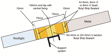
Built up system end lap detail (metal over GRP rooflight), three runs of butyl sealant
The position and size of butyl mastic seal in the overlap joints of outer sheets can have a significant effect on the overall performance and weather tightness of profiled roofing and cladding systems. The sealing strip is introduced into the lap to prevent the ingress of dirt and water from the weather side and to prevent the potential risk of condensate from entering the top of the lap from the inside.
The sealing strip or bead must be in full contact with both surfaces of the joint; it must be flexible enough to deform around the shape of the profile, resilient enough not to compress excessively under load and yet be flexible enough to withstand movement within the joint. The expansion characteristics of the sealant must be able to accommodate the full movement of the joint and therefore must be specified accordingly. It must also last the life of the building without degrading or cracking.
Q3 What is the correct method of installing insulation quilt?
Site assembled built-up cladding systems offer the advantage of being able to tailor the thermal and acoustic layers to meet the needs of the specific building. The correct installation of insulation quilt in built-up cladding systems will result in a more thermally and acoustically efficient building.
The design process assumes that the individual strips and elements of the insulation quilt are closely butted and form a continuous and unbroken layer across the whole surface of the building, including corners and junctions, thus ensuring all voids and gaps are filled with quilt insulation. It also assumes that the insulation layers rise to their full thickness without leaving a gap under the top sheet.
The insulation needs to fully fill the cavity and the top sheets should rest on the insulation or slightly compact the insulation when fixed. The insulation must not be permanently compressed or deformed locally as to adversely influence the final performance.
Q4 What are spacer systems?
The advantages offered by site assembled built-up cladding systems rely on the need to provide and maintain a space between inner lining and the outer sheet of the system to accommodate the insulation layer. The stand-off distance is governed by a spacer system which is made up of a structural bar and a series of structural posts or brackets. The posts are available in a range of different heights to suit the uncompressed depth of the insulation, which has been specified. Modern spacer systems are designed and engineered to not only provide a stand-off dimension but to also transfer the applied loads from the outside of the building through onto the primary and secondary internal structure. The spacer systems along with the cladding sheets also spread the load and provide a degree of stability to the supporting structure.
The posts of the spacer system are positioned along the length of the structural bar in accordance with the manufacturers’ instructions and they are attached at their base through the lining sheet and into the purlin with the required number of appropriate fasteners. Care must be taken to ensure that the fasteners, which form a structural part of the total system, are fully engaged into the top flange of the purlin.
Some types of spacer system require the introduction of additional structural bracing to accommodate particular loading conditions and manufacturers’ recommendations should be followed in these cases. It is vitally important to ensure that the spacer system is constructed and fastened to provide the required level of structural performance.
Manufacturers’ information regarding bracket spacing, joint distance from end of bracket, placement and positioning of fasteners, anti-sway requirements and the use with horizontal cladding must be followed precisely.
Q5 What is the minimum material thickness for external fabrications?
The common materials used for fabrications with metal cladding systems are manufactured from the same materials as the roof and wall cladding that is, coated steel or aluminium. The fabrications can be in the same colour as the area or in a contrasting colour for aesthetic effect. The minimum material thicknesses for external fabrications generally adopted by the industry are 0.7mm for steel and 0.9mm for aluminium. Flat widths greater than around 200mm require a stiffening bend or backing with a rigid material. Wide girths of steel or aluminium, perhaps on fascias, can be given extra support, for example, by bonding to a ply or insulation board or by bonding on stiffeners to the reverse side. Large flat unsupported fabrications tend to ‘quilt’ at fasteners adversely affecting the appearance.
Q6 What is the correct specification for fasteners?
Approximately 40 percent of fasteners on industrial/commercial buildings are used in an exposed situation and will require weather sealing. However, the installation process can sometimes have an adverse influence on the final performance; one of the principal causes of failure is the miss-drilling of primary fasteners through the external weather skin resulting in the fastener not engaging into the underlying purlin or spacer. This will result in the fastener spinning, not fully compressing the sealing washer and hence the fastener will leak.
Primary fasteners must be drilled through the top sheet within the area of the top flange of the purlin or spacer. Purlins can rotate and sag under certain loading conditions or if sag rods have not been installed during the erection process. This will result in misalignment of the purlin and the increased possibility of miss-drilling of primary fasteners. Loose miss-drilled fasteners should be removed at the time of installation and corrective action taken.
MCRMA Technical Paper No 12 entitled Fasteners for Metal Roof and Wall Cladding: Design, Detailing and Installation Guide deals with this subject in depth and should be regarded as the initial source of information about the generic subject of fasteners for the metal cladding sector. The document should be read in conjunction with published information available from the principal fastener manufacturers and also the current version of BS 5427: Part 1 Code of practice for the use of profiled sheet for roof and wall cladding on buildings. These documents spell out in detail how fasteners should be specified, the environmental and physical conditions which they may encounter and also how they should be used in various applications.
Q7 What are the loads and forces on individual fasteners?
The loads and forces on individual fasteners can generally be categories in three main groups, pullout resistance, pullover resistance and shear force resistance.
Pullout resistance is the ability of a fastener’s connection within its supporting material to remain intact and resist the axial and tensile loadings. As the UK metal cladding market frequently involves primary fixing into relatively thin cold rolled purlins, rails and spacing systems, pullout of primary fasteners is often the most critical of the loadings that should be considered. BS5427: Part 1 gives some typical methods for testing the pullout strength of fasteners and there are various other internationally recognised and accepted industry tests adopted by manufacturers.
Pullover resistance is the ability of the fastener to prevent the sheet material failing by pulling over the head of the fastener. This is rarely an issue in today’s metal cladding market however; pullover resistance of fasteners should always be considered particularly within applications incorporating thin gauge materials, GRP/PVC profiles, and applications including support structures thicker than 1.5mm, as pullover failure may occur at a lower value than pullout failure.
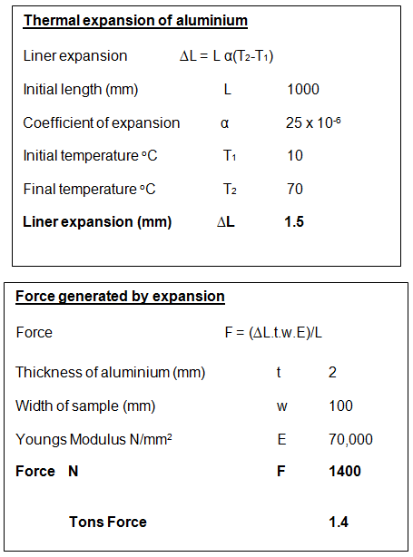
Shear force resistance on fasteners within metal roofing systems is not generally regarded as something which will adversely affect the performance of the system. However, the thermal expansion of metal cladding system and in particular aluminium systems can induce significant shear forces into the fasteners if not adequately accounted for or designed for. The calculation (see illustrations below) demonstrates how much an aluminium section can expand and, if not allowed for, how that expansion can generate a significant shear force on the fastener or tearing of the adjoining material.
Q8 What is the correct sequencing of composite panels to minimise gaps at junctions?
When installing composite panels it is important that the side underlap and overlap of the panels are correctly sequenced to enable the panels to sit or nest together without forming a gap in the joint. This is particularly important when underlaps and overlaps occur at junctions of side and end laps ie, a four point joint. Incorrect sequencing of the panels can result in this joint or junction having holes or gaps, which would allow water to enter into the building unless large quantities of sealant are used.
The adoption of the correct installation sequence can minimise the gaps and can result in a robust watertight joint. Composite panels, which may be prone to this characteristic, should be installed in columns starting at the eaves and working up the slope to the ridge. The adjacent column of panels should then be installed in the same way ensuring that the side overlap nests over the underlap on the adjacent panel.
During the installation sequence seals and fasteners must be built-in and fitted accordingly. Composite panels which have this distinguishing feature should not be installed in a step formation where each row of panels, starting at the eaves, is incrementally advanced across the roof. The diagram below demonstrates the difference and highlights the correct method of installation.
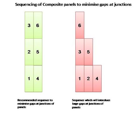
Composite panel layout direction
Q9 How much expansion should be allowed for when specifying aluminium flashings and profiles?
During the design and installation phase it is important to recognise that for aluminium flashings and profiles there is a need to incorporate a degree of expansion. A rule of thumb for thermal movement in aluminium is 1mm per metre of length. For dark colours this should be increased to 1.5mm per metre.
For example, a 3 metre flashing in a light colour needs an allowance of 3mm at each end for movement. In flashings and standing seams if expansion joints are not used and joints are rigidly fixed, the fabrication will act like a very long section amplifying the movement.
For example, four 3 metre sections fixed rigidly together will act like a 12 metre fabrication with 12mm of expansion/contraction trying to happen in a stiff material. If the expansion/contraction is not allowed to happen, temperature variations will cause thinner fabrications to ripple and buckle, laps and fasteners could weaken and leaks occur. Ultimately, fabrications could detach. In extreme cases, it has been known for rigidly fixed aluminium fabrications to fracture.
Q10 What factors do I need to consider when specifying surface coatings?
Modern roof and wall cladding systems offer specifiers and clients with the opportunity to explore a wide range of styles and colours to provide aesthetically pleasing buildings that blend or contrast with their surroundings. When specifying roofing and cladding systems it is also important to consider the type of surface coating to ensure that it will provide long term performance in its surrounding environment and to ensure that the material has a robust manufacturer’s backed guarantee.
Wide choices of surface coatings are available in both smooth and textured finishes and some coatings are also produced with a matt, gloss or metallic appearance. The choice of coating can also have an influence on how the panels are stored and handled on-site. The less robust coating systems will require more careful handling procedures and in some cases the specification of a strippable film, which must be removed soon after installation, would be advantageous.
The choice of surface coating can also influence the sequencing of maintenance programmes, the long term sustainability of the building envelope and hence the in service cost model. More detailed advice on these aspects can be obtained by contacting the system suppliers and material suppliers featured within the members section of the MCRMA web site.
Q11 Who needs to consider the risks when there is a requirement to work at height?
The Construction (Design and Management) Regulations CDM 2015 cover all construction work including maintenance of buildings, placing direct responsibility on building owners, as well as designers. This requirement links to the 2005 Work at Height Regulations (WAHR) which applies to all work at height where there is any risk of a fall liable to cause injury. It places duties on employers, the self-employed and any person who controls the work of others, such as facilities managers or building owners.
Q12 When considering the need to work at height what measures should be taken to minimise the risk?
There is a simple hierarchy for managing and selecting equipment for work at height. Duty holders must:
- Avoid work at height where they can
- Use work equipment or other measures to prevent falls where they cannot avoid working at height
- Where they cannot eliminate the risk of a fall, use work equipment or other measures to minimise the distance and consequences of a fall should one occur.
Q13 I am in the process of specifying fall protection equipment for a building. What additional questions should I ask of the supplier?
- Has the system been proven to work on the intended roof build up?
- Is there test data available to support this?
- Does the system comply with required testing standards?
- Will the system design accommodate unknown user competency and foreseeable misuse?
- Will the roof guarantee be affected by the fall protection being installed?
- How many people can the system provide fall protection for?
Q14 Are all industry guarantees, 'third party' guarantees, extended guarantees or warranties the same and what restrictions should I be aware of?
In many cases these types of guarantees or warranties are insurance backed and therefore involve payment of a premium. Some systems may include the following caveats:
- Restricted operating conditions, which fall outside of those normally encountered in the environment in which the products or systems are operating
- The need for formal documented inspections
- Inspections may incur a fee which is payable by the client or customer
- The need for documented annual maintenance programmes
- Early and prompt notification, in writing, of any damage, failure or non-conformity
Please refer to the MCRMA guidance document on this subject
Q15 Will the adoption of deeper cladding system have an effect on the supporting structure?
The following scenarios need to be considered when designing and specifying the solution:
- Ability of the cladding systems to transfer down-slope loads to the purlins
- Ensuring the purlins (or rails) are correctly aligned to accept the fasteners
- Ability of the cladding to provide a degree of restraint to the purlins (or rails) against wind uplift (or suction) loads
- Maintaining close steelwork tolerances to ensure airtightness of the building envelope.
- Ability of the secondary steel to support increased weight.
Any uncertainty about the use or application of a product or system should be referred back to the manufacturer for detailed written advice. Manufacturers are best placed to offer advice about their particular products and any variation from their published data during the design or construction process could result in the component or system failing prematurely or not complying with the guarantee or warranty conditions. Additional project specific advice for demanding or complex constructions may also be obtained from one of the independent consultants featured on the MCRMA web site.


